

For the Tivo I was building I had to build a driver for a standard HD44780 character LCD screen (up to 4x20 characters). I started from the excellent work by ch424 and all of the contributors to his thread at bit-tech. He was even kind enough to give me the source code for his microchip.
Well, I had never really made a circuit before, and I had definitely never programmed a microchip before, so I wanted to have a go at re-doing his work to better suit my needs and wants. So I completely re-designed his circuit and re-coded the entire project. I definitely used his code and circuit as a starting point, but I reworked every part of it to be my own. Additionally I received help from the RPI Electronics Club.
Capabilities
- Controls any HD44780 or KS0066U compatible LCD screen with at most 4x20 characters*
- Connects and is powered with USB (+5V, ~125mA)
- Emulates a serial port and can be used with the very powerful LCD Smartie software
- Up to 5 digital inputs (e.g. buttons) and 5 PWM outputs (e.g. LEDs and buzzers)
- Backlight and contrast can be changed in real-time through software
- Button presses send upper-case letters and releases send lower-case letters
- Reading the current state of the LCD, including:
the text on the screen, the custom characters, the state of buttons, etc - Saving default for use during boot-up, including:
the text, custom characters, backlight and contrast levels, output states, etc - Has an optional bootloader so firmware can be updated through standard USB (the bootloader requires a PIC programmer though)
* May work with KS0073. Will not work with T6963C or KS0066FF00.
Change Log
- Version 1.2.3: Minor update to software only, no changes to firmware
- BUG: LCD-Setter and LCD Smartie driver registry code needed some more fixing
- Version 1.2.2: Minor update to software only, no changes to firmware
- BUG: LCD-Setter and LCD Smartie driver registry code needed some fixing
- Made some 'invisible' changes in preparation for v2.0 (with support for 4x40 displays)!
- Version 1.2.1: Minor update to software only, no changes to firmware
- BUG: LCD-Setter and LCD Smartie driver used WMI to find the USB2LCD+ (requires administrator privileges), now uses the registry
- BUG: LCD-Setter would not report the COM port that caused errors
- Version 1.2:
Note: LCD-Setter and display driver are ONLY compatible with bootloader and firmware v1.2 or newer- Added a programmable ID to the chip so you can uniquely identify each USB2LCD+
- Firmware updating is much more reliable now with more than one USB2LCD+
- Display driver can use the programmable ID to select a particular USB2LCD+
- BUG: The read version and module commands used the wrong values
- BUG: Bootloader now reports versions similar to firmware
- Version 1.1:
- Added a bootloader and adjusted the main firmware to support this
- BUG: Startup message was showing while the computer was off or while USB was suspended
- BUG: Backlight/contrast/GPO updating was not happening until the computer had fully turned on
- BUG: Interrupt timer was always on even if unnecessary
- BUG: Problems with Windows driver
- BUG: COM Security error for the LCD Smartie display driver
- BUG: Special characters not being sent to LCD from LCD-Setter
Future Work
- Add support for 4x40 character LCD screens
Microchip
The circuit uses a PIC18F2550 DIP28. With little or no changes to the code PIC18F2455/4455/4550 may also be used. The program is written in C18. It uses separate bootloader and firmware programs. The bootloader loads first and in particular situations enters "update mode" allowing a new firmware to be easily installed onto the chip. The firmware does most of the work.
Bootloader: hex (5.17 KB, updated 2012-11-08) or source (77.71 KB, updated 2012-11-08)
Firmware: hex (39.59 KB, updated 2012-11-08) or source (122.71 KB, updated 2012-11-08)
Note: The bootloader is optional. The firmware can be applied directly with a PIC programmer. If you do not have the bootloader, any firmware updates will need to be applied with a PIC programmer as well.
Programming the Microchip
To install the bootloader onto the PIC you will need to buy, make, or borrow a PIC programmer. A tutorial is available from ObdDiag.net. You need to make sure to set the programmer configuration as in this image. Especially important is the USB voltage regulator setting. I may have actually compiled these into the bootloader hex file above, but I am not sure.
When plugging in the USB device you will need to install the MCHPUSB driver from Microchip to recognize the device in bootloader mode. Then use the LCD-Setter program to install the firmware. To update the firmware in the future all you have to do is use the LCD-Setter program.
Download MCHPUSB Bootloader Driver (67.27 KB, updated 2012-11-08)
Pinout
![[PIC18F2550 Pinout]](pic.png)
Where MCLR is the clear pin, BL- is the backlight ground, IN# are inputs, OUT# are output pins, RB ports are the 8 pins to the LCD, OSC1/2 are the clock pins connected to a 4 MHz crystal, VDD is +5V from USB, VSS is ground, D+/D- are USB data pins, and VUSB is the voltage regulator.
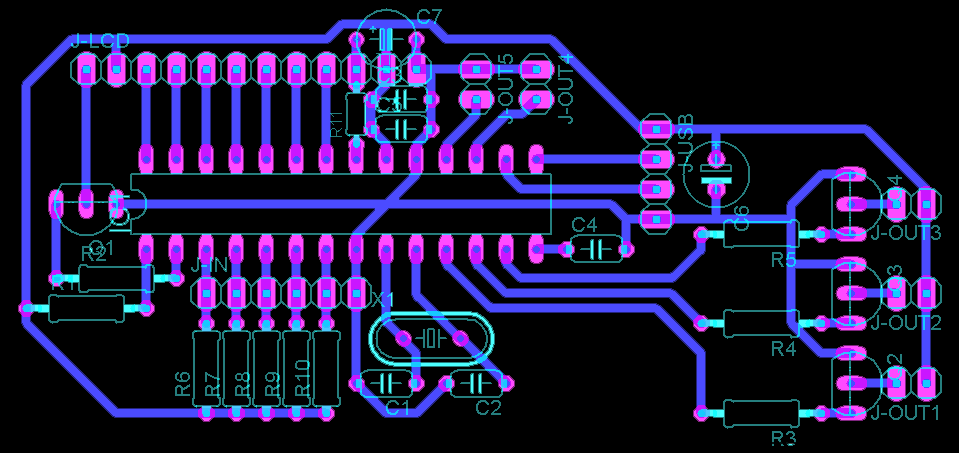
The Circuit
The circuit was designed using Cadsoft Eagle Free. Here is the board I designed:
![[USB2LCD+ Board]](board-small.png) View larger image (16.79 KB, updated 2012-11-08)
Download Eagle schematic (309.55 KB, updated 2012-11-08)
Download Eagle board (24.66 KB, updated 2012-11-08)
View larger image (16.79 KB, updated 2012-11-08)
Download Eagle schematic (309.55 KB, updated 2012-11-08)
Download Eagle board (24.66 KB, updated 2012-11-08)
Components
- R1, R6-R10:10k
- R2-R5:4k7
- R11:1001
- C1, C2:22pF2
- C3, C5:100nF
- C4:220nF
- C6, C7:100uF
- Q1-Q4:BC184L3
- X1:4MHz2
- IC1:PIC18F2550 DIP28
Note 1: The contrast resistor R11 may need to be adjusted for your LCD.
Note 2: You may replace C1, C2, and X1 (the crystal clock) with a ceramic resonator.
Note 3: Any bipolar NPN transistor (BC547(B), BC548(A/B), (2S)C1815, ...) will likely work for Q1-Q4, just make sure to adjust for the order of the pins and the base pin resistor (R2-R5).
Note 4: Some LCDs require a resistor for the backlight pins.
Connectors
- J-LCD:BL- BL+ D7 D6 D5 D4 EN RW RS CT VDD VSS (left to right)
- J-USB:VCC/Red D-/White D+/Green GND/Black (top to bottom)
- J-IN:IN1 IN2 IN3 IN4 IN5 GND (left to right, all inputs will use the same ground)
- J-OUT 1-3:GND VCC (left to right, these provide higher currents)
- J-OUT 4-5:VCC GND (top to bottom, these provide lower currents)
The difference between the two types of OUT are that 1-3 draw current directly from the USB port (suitable for fans) and 4-5 draw current through the chip (suitable for LEDs). You can make any of them how you want (high or low current draw). If you use the transistor setup it will allow more current draw. Also note that the GND and VCC are kinda backwards between the two types.
Connecting to the Computer
Once the firmware is installed a different driver is needed. For Windows XP/Vista/Windows 7 (32 or 64 bit) you can use the driver below. You will get an unsigned driver warning, but can safely ignore it. It is actually using a serial emulation driver built into Windows. You will get a new USB2LCD+ Communications Port which you can use as a normal serial port.
Note: For Vista 64 you need to install the certificate included. In XP / Vista 32 / Windows 7 this removes all unsigned driver warnings. To install the certificate, do the following BEFORE installing the driver:
- Double click usb2lcd.cat (it is in the zip file with the INF file)
- Click "View Signature"
- Click "View Certificate"
- Click "Install Certificate..."
- Click next a few of times, then Finish
- At the security warning click "Yes"
- Close all the windows
Linux supports this device natively*, and it shows up as /dev/ttyACM# (where # is some number, mine is 0). Sadly you will still need Windows to install the firmware the first time with the LCD-Setter program.
* Some distributions of Linux are missing the USB cdc-acm driver module and require additional setup.
Using LCD-Setter
I made a program that utilizes almost every feature of the USB2LCD+ interface. It is required to install or update the firmware on the chip. It is very useful for testing the circuit and code. Additionally it is the easiest way to set the startup message for the chip. It also comes with a utility library that has all the code for finding devices and updating the firmware. You need at least .NET Framework 2.0 to use the program. The program source code is written in C++/CLI and the utility DLL is in C++. It allows you to define what characters your display actually uses so that you can see what the output will look like.
Download LCD Setter Application (43.63 KB, updated 2012-11-08) Download LCD Setter Source Code (111.74 KB, updated 2012-11-08)Using LCD Smartie
Use the Matrix display driver, set the COM port appropriately, and you should be all good to go!
Or you can use a custom driver I made for LCD Smartie. The custom driver has slightly better performance, a little more power, and you don't need to know the COM port. It is able to find which COM port it is on it's own (which is really nice if you plug the LCD into different USB ports and the COM port changes). To install just download the DLL file and put it in the "displays" folder of LCD Smartie, then restart LCD Smartie and select the USB2LCD driver in the setup.
Download USB2LCD+ LCD Smartie Driver (11.5 KB, updated 2012-11-08) Download Visual C++ Project for Display Driver (23.63 KB, updated 2012-11-08)Using Custom Commands
There is a very long list of commands that are supported by this program. The commands are used by sending special characters over the serial connection and can be used from a custom made program, from a terminal (cmd.exe, bash, etc), from a program like Hyperterminal or SecureCRT, or from within LCD Smartie with $Chr(). Anything that does not start with a 254 character will be printed to the screen. Here is the brief list:
- Display on:254 66 [mins:0-255] (if 0 then it is indefinitely on)
- Display off:254 70
- Cursor on:254 74
- Cursor off:254 75
- Blink on:254 83
- Blink off:254 84
- Position:254 71 [col:1-20] [row:1-4]
- Home:254 72
- Clear display:254 88
- Define custom:254 78 [c:0-7] [8 bytes]
- Backlight:254 152 [value:0-255]
- Contrast:254 80 [value:0-255]
- Output on:254 87 [1-5]
- Output off:254 86 [1-5]
- Output PWM:254 102 [1-5] [value:0-255]
- The char 254:254 254
Terminal examples:
echo Hello World! > \\.\COM8printf "\xFE\x47\x1\x1Hello World!" > /dev/ttyACM0
Troubleshooting
A number of problems can occur while building the USB2LCD+. As I get emails with questions, I will post the most common problems and solutions here.
The most common is the following error in Windows:

If this happens before you install the firmware it is most likely that the bootloader was not installed properly or part of the circuit is not setup correctly. The components that can cause this are C4, X1/C1/C2, C3/C5, C6, or R1. Other components are not required before the firmware is installed.
If you get this error after installing the firmware it is most likely that the LCD is not properly connected in the circuit. The firmware freezes if it cannot communicate with the LCD. When the firmware freezes, the USB connection freezes, which causes Windows to complain.